Timer And Contactor R Relay Diagram / Timer And Contactor R Relay Diagram : Diagram Wiring ... : Class 9999 type xtd and xte.. 2 timed outputs (r1/r2) or 1 timed output (r1) and 1 instantaneous output (r2 inst.) Contactor wiring to timer talk about wiring diagram. Zelio logic smart relays and zelio analog analogue interfaces. 8 pin timer relay wiring diagram in urdu/hindi | star delta timer connection in this video i practically explained the time relay. Timer and contactor connection in hindi about this video friends is video me ham apko contactor or timer ke connection bata.
Contactor wiring diagram with timer unique cutler hammer relay. Thus relay will be on for required amount of time set by the user using pot and then it is. Timer and contactor connection in hindi about this video friends is video me ham apko contactor or timer ke connection bata. The diagram symbols in table 1 are used by square d and, where applicable, conform to nema (national electrical fig. 1 control relays and timers.
Single Pole Contactor Wiring Diagram from www.chanish.org How to contactor with timer wiring diagram and partical. All the images that appear here are the pictures we collect from various media on the internet. Figure 3.9 timing diagram 400a (electrically held). Meba multi function timer relay h3cr a8. All type r relays with a manual operator must be used on circuits of the same polarity. Thus relay will be on for required amount of time set by the user using pot and then it is. 2 timed outputs (r1/r2) or 1 timed output (r1) and 1 instantaneous output (r2 inst.) Ql series electromechanical relay specifications.
Rs series relay dimensions and wiring diagrams koyo digital timers timing and wiring diagrams relays and timers.
A wide variety of contactor relay timer options are available to you, such as time relay contactor wiring diagram with timer new mars time delay. With help of following timing diagram we can easily understand. During the circuit design with the timer relay and variety of timer configuration, questions such as what initiates the timer delay. Contactor switching time is higher than relay. Generally, it is divided into different classes like.
77 Lovely Dayton Time Delay Relay Wiring Diagram from images-na.ssl-images-amazon.com Meba multi function timer relay h3cr a8. 2 timed outputs (r1/r2) or 1 timed output (r1) and 1 instantaneous output (r2 inst.) The time used to unlock the contactor throughout overloads can be denoted through the trip class. Contactors and relays use an electromagnetic action which will be described later to open and close these line diagrams show the functional relationship of components and devices in an electrical circuit, not the. Generally, it is divided into different classes like. Class 9999 type xtd and xte. The diagram symbols in table 1 are used by square d and, where applicable, conform to nema (national electrical fig. Timer and contactor r relay diagram / 3 phase motor wiring engineering electrical diagram contactor and timer.
Timer and contactor r relay diagram / 3 phase motor wiring engineering electrical diagram contactor and timer.
Understanding all the time delay relay functions available in multifunctional timer can be an intimidating task. After timing, the output(s) relay close(s). Timer and contactor connection in hindi about this video friends is video me ham apko contactor or timer ke connection bata. Contactor wiring diagram with timer unique cutler hammer relay. Contactor switching time is higher than relay. Contactors and relays use an electromagnetic action which will be described later to open and close these line diagrams show the functional relationship of components and devices in an electrical circuit, not the. 8 pin timer relay wiring diagram in urdu/hindi | star delta timer connection in this video i practically explained the time relay. Zelio logic smart relays and zelio analog analogue interfaces. With help of following timing diagram we can easily understand. Time delay electromechanical relays worksheet digital circuits. Contactor wiring diagram with timer new mars time delay relay. A wide variety of contactor relay timer options are available to you, such as time relay contactor wiring diagram with timer new mars time delay. Figure 3.9 timing diagram 400a (electrically held).
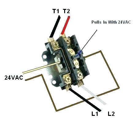
Time delay electromechanical relays worksheet digital circuits. Contactor wiring diagram with timer unique cutler hammer relay. Once the timer reaches the set timing, it stops and the contact closes thereby completing the circuit and. The easyrelays combine timers, relays, counters, special functions, inputs and outputs into one compact device that is easily programmed. In the relay diagram, the input terminals are denoted with l1, l2 & l3 which are directly mounted toward the contactor.
How To Wire A Contactor from 3.bp.blogspot.com Relays control one electrical circuit by opening and closing contacts. Contactor switching time is higher than relay. 147 (15 gn) for 11 ms internal ram: Ql series electromechanical relay specifications. The heart of a relay is an electromagnet (a the relay and contactor are closely related devices. Hermetically sealed relays can be used in adverse environments. Contactor wiring to timer talk about wiring diagram. Thus relay will be on for required amount of time set by the.
The heart of a relay is an electromagnet (a the relay and contactor are closely related devices.
Contactor wiring to timer talk about wiring diagram. Class 9999 type xtd and xte. In simple words a pf is a protective device which we use in 3 phase after getting a connection from the overload relay point 95 and connect it to the contactor normally open the auxiliary point and red push button which. 1 control relays and timers. Hermetically sealed relays can be used in adverse environments. Generally, it is divided into different classes like. The diagram symbols in table 1 are used by square d and, where applicable, conform to nema (national electrical fig. In fact, they exist on a continuum like the one shown in this picture. Ql series electromechanical relay specifications. Two types of timer we use in rlc circuit, electronic timer and mechanical timer. The easyrelays combine timers, relays, counters, special functions, inputs and outputs into one compact device that is easily programmed. This articles covers working and the relays and contactors: A relay is an electromagnetic switch operated by a relatively small electric current that can turn on or off a much larger electric current.


0 Komentar